A. Definition of Metallography Overview of Metallographic Inspection
Metallographic testing is widely used in the quality control process of casting parts, and die casting parts. It involves preparing a specimen surface by grinding and polishing (or chemical and electrochemical polishing) to a specified level of smoothness. Subsequently, the specimen is subjected to corrosion using specific etchants. The different corrosion rates in various phases or directions within the same phase reveal the characteristic features of each phase. This process utilizes optical instruments such as metallographic microscopes, magnifying glasses, and stereomicroscopes to analyze and characterize material microstructures, low-magnification structures, and fracture surfaces. Metallography is a branch of materials science that encompasses the imaging and qualitative and quantitative characterization of three-dimensional microstructures of materials. It also involves necessary sample preparation, handling, and sampling methods. The representative scale of observed material structures ranges from 10^-9 to 10^2 meters (typical magnification up to 1000 times and below). Metallography primarily reflects and characterizes the quantity, morphology, size, distribution, orientation, and spatial arrangement of phases and constituents, grains (including possible subgrains), non-metallic inclusions, and certain material defects (such as dislocations).
B. History of Metallographic Inspection
The history of metallographic techniques as a means of materials research dates back to 1863 when Henry Clifton Sorby, a British scientist, observed the metallographic structure of steel using a microscope. In 1864, he presented the first micrograph of steel. Optical microscopy subsequently became an effective tool for the study and inspection of steel materials. Currently, metallography remains the most widely applied and practical research and inspection method in the field of materials science and engineering. Metallographic inspection is recognized as a significant physical testing item in national and international materials inspection standards, including ISO standards.
C. Importance of Metallography
In Materials Science and Engineering, Metallography is considered the precursor to metallurgy and forms the foundation for the survival and development of metallurgy. The microscopic structure of steel materials serves as a bridge between material composition, processing, and performance. The study of the relationship between composition, processing, and performance has been a central theme in the research and development of steel materials for centuries. The diversity of steel material properties is closely related to the diverse and complex world of its microstructure, consisting of austenite, ferrite, pearlite, martensite, bainite, and various second phases.
D. Role of Metallographic Testing in Quality Control
The use of metal materials typically follows the interrelation of “composition-structure performance.” Metallography, or metallographic science, investigates the internal structure of metals or alloys. It also studies how external conditions or intrinsic factors affect the internal structure of metals or alloys. Intrinsic factors mainly refer to the chemical composition of metals or alloys, while external conditions include temperature, processing deformation, and casting conditions. It is well-known that alloy composition, heat treatment processes, and cold/hot working processes directly influence the internal structure and properties of metal materials, leading to changes in the mechanical performance of components.
Therefore, the method of using metallographic analysis to observe and inspect the internal structure of metals is an important means of industrial production. The commonly used metallographic observation and inspection can be divided into the following aspects:
Raw Material Inspection: Examination of the metallurgical quality of raw materials, including checking for segregation, types, and levels of non-metallic inclusions; inspection of casting materials for casting looseness, porosity, and uniformity of inclusion distribution; inspection of forged parts for surface decarburization, overheating, burning, cracks, deformation, etc.
Quality Control in Production Processes: Metallographic analysis can provide a basis for adjusting processes and modifying process parameters, guiding production decisions. For example, it can assess whether heat treatment quenching temperatures, holding times, and cooling rates are appropriate; control of chemical surface heat treatment process parameters; and whether the starting and ending forging temperatures are suitable.
Product Quality Inspection: Some mechanical parts or products not only require mechanical and physical performance indicators but also demand microscopic structure parameters as one of the technical indicators for quality assessment.
Failure Analysis: Metallographic structure analysis methods are widely used in the analysis of mechanical failures, making it convenient to identify common defects. Examples include surface decarburization of components, morphology and distribution characteristics of microscopic cracks, defects from chemical heat treatment, abnormal post-heat treatment structures, and the precipitation of brittle phases at grain boundaries. The results of these metallographic analyses are often used as a basis for failure analysis.
II. Basics of Metallography
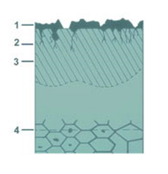
A. Overview of Microstructure
The internal structure of metals is composed of individual crystal regions called “grains.” The structure, size, and orientation of these grains depend on the material’s composition (alloy) and the manufacturing methods employed (such as forging, casting, or additive manufacturing). These grains form as the molten material solidifies and interacts with other substances and components, such as phases and impurities. Typically, grain structures need to be adjusted to suit technological applications.
The size, orientation, and other structural characteristics of grains directly impact the mechanical and technological properties of materials. Structural characteristics also depend on subsequent external influences. These influences include:
Chemical effects (such as corrosion)
Chemical and/or physical effects (such as heat treatment processes)
Mechanical effects (such as forging, rolling, bending after forming processes)
Microscopic structures can only be assessed through microscopes (stereomicroscopes, optical microscopes using reflected light, digital microscopes, or scanning and transmission electron microscopes). Typically, observed feature sizes range from millimeters to micrometers, and even nanometers. Microscopic structure observations are widely used in various studies, such as determining grain size, inspecting defects, preparing microelectronic targets, and various welding and failure analyses.
B. Crystal Structure
The most fundamental unit in the microstructure of metals is the crystal. A crystal is a solid formed by the orderly arrangement of atoms, ions, or molecules in space. Each crystal has a specific crystal structure, where the arrangement and periodic properties of atoms determine the material’s performance. Common crystal structures include:
Face-Centered Cubic Structure (FCC): Found in metals like aluminum and copper, where atoms align along the faces of each cube.
Body-Centered Cubic Structure (BCC): Typical examples include iron, where one atom is located at the center of each cube.
Hexagonal Close-Packed Structure (HCP): Found in some metals like titanium and zirconium, where atoms are closely packed in a hexagonal arrangement.
C. Steps in Metallographic Testing
Metallographic testing typically involves the following steps:
Sample Preparation: Prepare metallographic test samples by cutting, grinding, and polishing to ensure a smooth surface.
Etching: Expose the sample to specific etchants to highlight features of different grains or phases.
Rinsing and Cleaning: Wash and clean the sample to remove etchants and other impurities.
Microscopic Observation: Use tools such as metallographic microscopes to observe the microstructure of the sample, including the shape, size, and distribution of grains.
Analysis and Recording: Analyze the observed structures and record information about grains, phases, and other structural features.
Executing these steps requires specific expertise and skills to ensure accurate and reliable metallographic analysis results. The application of metallography in the field of materials science and engineering provides a crucial means for understanding material performance and quality control.
D. Significance of Microstructural Analysis
Applications of Metallographic Microscopy in Metal Material Inspection:
Grain Structure Analysis: Metal materials are typically composed of multiple grains, each with its own crystal structure. Metallographic microscopes can observe the distribution, shape, and size of these grains. Analyzing grain characteristics allows inference about the material’s preparation process, processing history, and potential heat treatment effects.
Grain Boundary Analysis: Grain boundaries, the boundaries between adjacent grains, significantly influence the strength, plasticity, and corrosion resistance of metal materials. Metallographic microscopes can assist in observing the types, density, and distribution of grain boundaries, enabling the evaluation of material grain boundary properties.
Defect Detection: Various defects such as pores, inclusions, and cracks may exist in metal materials. These defects can lead to increased brittleness and reduced strength. Metallographic microscopes can help detect these defects and analyze their shape, size, and distribution, aiding in the assessment of material quality.
Phase Transformation Studies: Metals may undergo phase transformations, changing their crystal structure under different temperatures and pressures. Metallographic microscopes can track the microscopic structural changes during phase transformations, aiding in understanding the mechanisms and optimizing material performance.
Microstructure Evolution Analysis: Microscopic structures of metal materials may change during use, such as through processing or stress. Metallographic microscopes can track these changes, assisting researchers in understanding the evolution of material structures under different conditions.
Material Hardness Evaluation: Metallographic microscopes can be used to observe the microhardness distribution of materials, allowing the assessment of hardness variations in different regions. This is crucial for determining the localized properties of materials.
Metal Corrosion Analysis: The corrosion performance of metal materials is related to their microstructure and organization. Metallographic microscopes can help observe the distribution of corrosion products, analyze corrosion mechanisms, and predict material corrosion behavior in different environments.
Welding and Heat Treatment Analysis: Metallographic microscopes can analyze the microscopic structure of welded joints to evaluate the quality of welds. Additionally, they assist researchers in optimizing heat treatment processes and controlling grain size and organization.
E. Applications of Metallographic Analysis Methods:
Welding Metallographic Inspection
Cast Iron Metallographic Inspection
Heat Treatment Quality Inspection
Microscopic Structure Inspection and Assessment of Various Metal Products and Raw Materials
Low Magnification Defect Inspection for Cast Iron, Cast Steel, Nonferrous Metals, and Raw Materials
Metal Hardness (HV, HRC, HB, HL) Measurement, Grain Size Grading
Determination of Non-Metallic Inclusion Content
Measurement of Decarburization Layer/Carburized Hardening Depth, etc.
III. Metallographic Steps and Procedures
A. Sample PreparationSampling Principles:
Selected samples must represent the nature of the parent material.
The location of metallographic sampling may vary based on the inspected metal material or part’s process, treatment, inspection purposes, and technical agreements between parties.
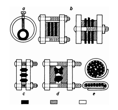
(2) Embedding for Metallographic Sample Preparation
Purpose of Embedding: Embedding is employed for small-sized or irregularly shaped samples such as ribbon samples or tubes that are challenging to hold manually. It is also used when inspecting edges and for standardized semi-automatic sample preparation.
Methods of Embedding:
Hot Embedding: Advantages include high quality, uniform size and shape, time-saving, and cost-effectiveness. The process is not suitable for quenched and tempered steels, especially for certain softer materials prone to plastic deformation under pressure.
Cold Embedding: Convenient, flexible, and suitable for various-shaped samples. Samples are placed in molds, and embedding occurs through a chemical catalytic process.
Mechanical Clamping: Embedding the sample into steel rings or clamps. The sample should have close contact with the steel, and the hardness of the fixture should be close to that of the sample.
2. Grinding and Polishing:Purpose of Grinding:
To remove damaged or deformation layers and obtain a flat surface with minimal damage. Generally, it involves two steps: rough grinding and fine grinding.
(1) Rough Grinding (Grinding):
Uses an abrasive wheel to remove cutting heat-affected zones or deformations and achieve a flat surface. Cooling with water during grinding is essential to prevent structural changes.
(2) Fine Grinding (Polishing):
Eliminates deeper abrasions in preparation for sample polishing. Different types of SiC sandpaper and diamond grinding discs are used sequentially: 280-grit SiC paper, 400-grit SiC paper, 500-grit, 600-grit, and 800-grit metallographic sandpaper. The sample should rotate 90° with each paper change to ensure complete removal of previous abrasions.
(3) Polishing:
The final step removes fine-grinding scratches, creating a smooth, flawless mirror surface.
Divided into mechanical polishing, electrolytic polishing, and chemical polishing.
Mechanical Polishing: Uses polishing fabrics of varying coarseness for rough and fine polishing.
Coarse polishing: Nylon, canvas, woolen cloth.
Fine polishing: Velvet, silk, nylon fabric, velvet.
Electrolytic Polishing: Based on the principle of anodic dissolution, with the sample as the anode and stainless steel or zinc as the cathode. Parameters include voltage, current, temperature, electrolyte, and polishing time.
Chemical Polishing: Relies on uneven dissolution of the sample surface using chemical agents to gradually achieve a bright surface.
3. Etching Techniques
Purpose of Etching: The purpose of immersion etching is to reveal the true and clear microstructure of the material.
Methods:
Chemical Etching
Principle: Utilizes the solution of chemical reagents to demonstrate the metal’s microstructure through chemical or electrochemical reactions.
Methods: Immersion etching and swabbing.
Electrolytic Etching
Application: Used for alloys with high chemical stability where the microstructure is challenging to reveal clearly using chemical etching methods. Examples include stainless steel, heat-resistant steel, high-temperature alloys, and thermocouple materials.
Principle: Essentially similar to electrolytic polishing.
Etching Effects: Determined by a combination of voltage, current, temperature, electrolyte, and etching time.
Key Points: Before etching, the sample surface must be thoroughly cleaned, removing any dirt or impurities.
Special Techniques:
Coloring: Adding color to the etching solution to enhance the visibility of certain features.
Cathodic Vacuum Etching: A specialized method for creating specific etching effects using a vacuum.
IV. Metallographic Testing Equipment
A. Overview of Basic Equipment
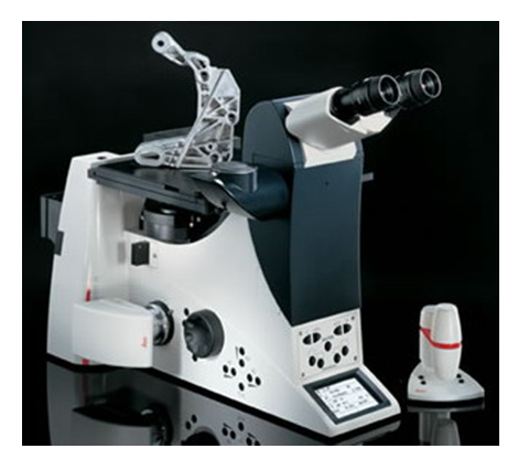
1. Introduction to Metallographic Microscope
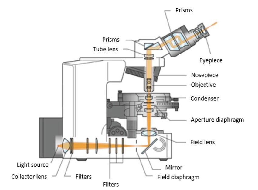
A metallographic microscope is an essential tool for examining the microstructure and organization of metal materials. As the properties of metal materials are often influenced by their microstructure, this microscope plays a crucial role in exploring details such as grain structure, grain boundary characteristics, and defects. Through metallographic microscope testing, valuable information about a material’s research, production, and application can be obtained.
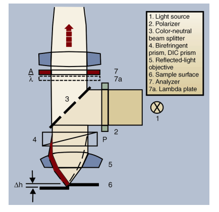
Working Principle:
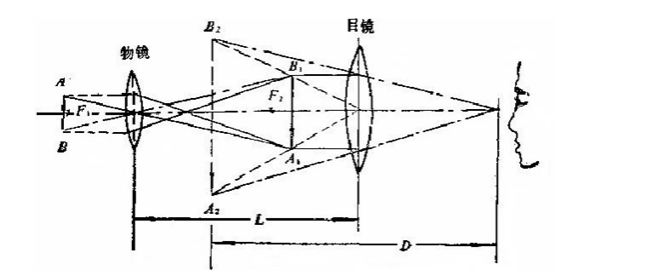
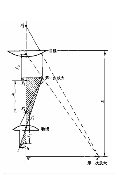
Optical metallographic microscopes have a two-stage magnification function: the structural details on the object are magnified first by the objective lens and then by the eyepiece for a second time.
AB represents the object to be magnified, placed between one and two times the focal length of the objective lens (with f1 being the front focal length of the objective).
The first magnified image AB’ is an inverted real image.
Image AB must fall within one times the focal length (f2) of the eyepiece. It is then magnified by the eyepiece to become an erect virtual image A’B”.
The total magnification of the microscope is the product of the magnifications of the objective and eyepiece.
Types of Microscopy:
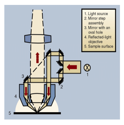
Bright Field Microscopy (BF):
The illumination light is directly shone onto the sample surface, and the reflected light is observed.
Commonly used and provides a realistic display of various tissue morphologies.
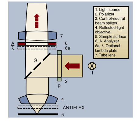
Polarizing Microscopy:
Utilizes polarizing filters to examine substances with birefringence when viewed orthogonally.
Applicable for discriminating geological rock phases and crystallographic inclusions.
Dark Field Microscopy (DF):
Utilizes the phenomenon of light diffraction/deflection, creating a specific illumination by using oblique lighting.
Allows observation of substances that may not be visible in bright fields.
Invented by Nomarski in 1952, it enhances contrast by utilizing the interference phenomenon of linearly polarized light passing through a Nomarski prism.
Improves the observation of certain tissue structures and provides a stronger three-dimensional sense.
B. Examination of Microstructures
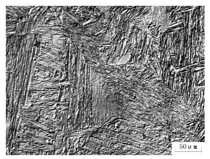
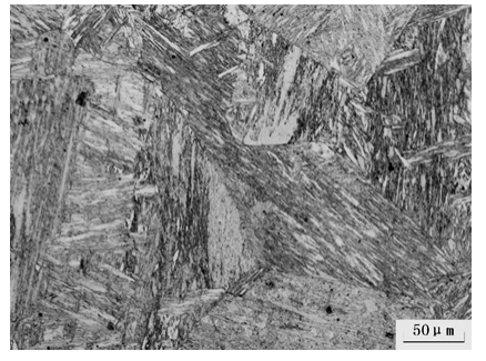
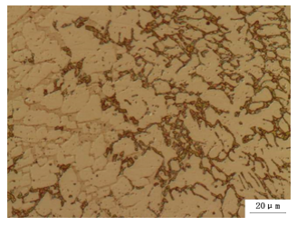
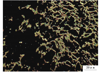
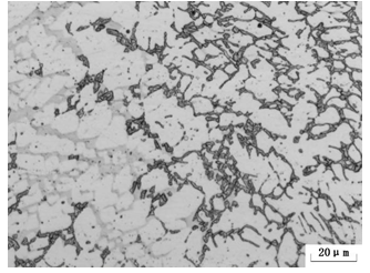
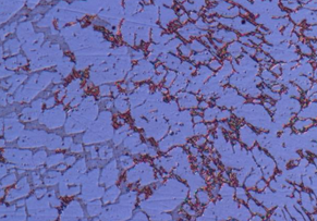
1. Documentation of Images Observed Under the Metallographic Microscope
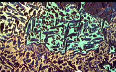
DIC 17CrNiMo6
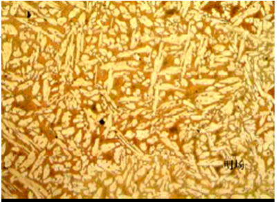
Bright Field 17CrNiMo6
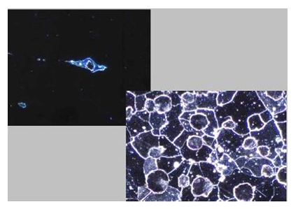
Polarizing Microscopy
Dark Field Microscopy
Bright Field Microscopy
DIC Microscopy
2. Principles and Applications of Microhardness Testing
Principle:
Microhardness testing involves pressing a diamond indenter with a specific geometric shape into the surface of the test material under a relatively small load, followed by optical measurement of the diagonal of the resulting impression. Due to the small scale of the indentation, measurements must be conducted under a microscope. The applied load is relatively small, hence the term “microhardness.”
Applications:
Microhardness testing is utilized for various purposes, including determining the hardness of chemical heat-treated layers, surface coatings, and specific phases or constituents in microstructures. It is also employed to assess the hardness of extremely soft or hard materials.
Indenter Types and Microhardness Values
There are two main types of indenters used in microhardness testing, each associated with specific hardness measurement values:
Vickers Indenter
Shape: Pyramid with a square base (正方锥体)
Symbol: HV (Hardness Vickers)
Formula:
Notation: HVO.1, HV1.0 (Representing different scales)
Explanation: The Vickers microhardness value is calculated by dividing the applied load (P) by the surface area of the indentation (A).
Knoop Indenter
Shape: Rhombic pyramid (菱面锥体)
Symbol: HK (Hardness Knoop)
Formula:
Notation: HK0.1, HK1.0 (Representing different scales)
Explanation: Similar to Vickers, the Knoop microhardness value is calculated by dividing the applied load (P) by the surface area of the indentation (A).
Note: In the formulas, P represents the load applied on the microindenter, and A represents the surface area of the resulting indentation.
These microhardness values provide insights into the hardness characteristics of materials at a microscopic level and are crucial for understanding material properties and behaviors in various applications.
Components of Microhardness Tester:
Frame
Optical system
Loading system
Stage
Measurement system
Factors Affecting Microhardness Values:
Measurement errors
Surface condition of the specimen
Test location
Test load
Loading rate and dwell time
Related Equipment:
Microhardness Tester
Mounting Press
Grinding and Polishing Machine
Etching Solutions
3. Considerations in Metallographic Analysis
Multiscale Nature of Material Microstructures:
Various hierarchical levels, including atomic and molecular scales, crystal defects such as dislocations, microstructures of grains, subgrain structures, and macroscopic structures, should be considered in material microstructural analysis.
Inhomogeneity in Material Microstructures:
Real microstructures often exhibit geometric irregularities, uneven distribution of chemical components, and variations in microscopic properties like microhardness and local electrochemical potential.
Directionality in Material Microstructures:
Addressing anisotropy in aspects like grain shape, orientation of low-angle boundaries, crystallographic preferred orientation (texture), and the directional nature of macroscopic material properties is essential. Analyzing and characterizing these directional features separately is necessary.
Variability in Material Microstructures:
Changes in chemical composition, external factors, and time can induce phase transformations and structural evolutions in material microstructures. Apart from static qualitative and quantitative analyses, attention must be given to investigating the necessity for studying the kinetics and mechanisms of microstructural evolution and solid-state phase transitions.
Fractal Characteristics and Resolution Dependence:
Material microstructures may exhibit fractal properties, and the quantitative analysis results can be highly dependent on image resolution. It is crucial to be aware of the resolution dependence, especially during quantitative analysis of material fracture surface morphology and when storing or processing digital images of microstructures.
Limitations of Non-quantitative Studies of Material Microstructures:
While qualitative studies of microstructures may sometimes meet the requirements of materials engineering, material science analysis often demands quantitative determination of geometric features. Additionally, error analysis, including consideration of random errors, systematic errors, and outliers, should accompany quantitative results.
Limitations in Cross-Sectional or Projected Observation of Material Microstructures:
The observed limitations in cross-sectional or projected images of material microstructures, such as those seen in the three-dimensional structures of cast iron graphite and pearlite, can lead to misinterpretations. Careful consideration of these limitations is essential to avoid misjudgments in interpreting images.